DIY materials required for DIY:
5×10K resistor
1×28p narrow body chip holder
5× momentary switch
1×0.1uf capacitor
2×100uf capacitor
1 power outlet
1× slide switch
1× audio jack
2 x 2 inch copper wire
1×TEA5767 radio module
1×ATmega328 inline
1×7cm×5cm hole plate
2 x 68 ohm resistor
2×3.3k resistor
1×5v 1602 LCD
Production process:
1. Give TEA5767 radio module welding wire


2. Controller socket and TEA5767, the controller communicates with the TEA5767 via the I2C protocol. This is just an easy way to talk to the device with very few connections. Here, the SDA (green line) and symptom self-rating scale (yellow line) ports. Install TEA5767 radio module

Install 28p narrow body chip holder

Chipholder pin 27 is connected to pin 1 of the TEA5767.

Chipholder pin 28 is connected to pin 2 of TEA5767.

3, stereo audio output and capacitance, TEA5767 radio module 7 and 8 pins are stereo audio output pins (left and right respectively), connected to the audio output jack. Install the audio output jack
 Increase the capacitance (positive polarity pointing down)
 Solder the capacitor and connect it to the audio jack.
 Solder the capacitor at both ends of the 7 and 8 pin TEA5767.

Increase power (right) and ground (left)
 Ground wire ground

Soldering 5V power cord

4. Preset button, preset button tells the MCU whether to change the current frequency to save the frequency, or save the current frequency to the memory. Install momentary switch and 10K resistor

10K resistors have in common

Instantaneous switching of the power rail. Connect the green wires to each switch directly to the pins 4, 5, and 6.
5. Tuning switch. The tuning switch increments or decrements the 0.1 current frequency. Install momentary switch and 10K resistor

Welding grounding and power connection switch

Weld pins 23 and 24 to the top and bottom switches.
6, power socket, toggle switch, bypass capacitor. Next, we need to add a power outlet and slide switch control and power circuit. We also need to add a small bypass capacitor (0.1uF) between TEA5767 5V and GND. Welding power outlet power supply and ground wire


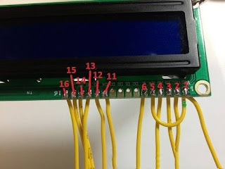
7, liquid crystal display output, we are now connected to the LCD screen motherboard and two resistors (3.3kΩ) and backlight (67 ohms) LCD screen. This part may cause some confusion, so pay close attention to the numbers.


8. Finally, solder a wire to the TEA5767 pin 10 as an antenna, and then find a case to wrap it, it will be OK. Finished product display:

5×10K resistor
1×28p narrow body chip holder
5× momentary switch
1×0.1uf capacitor
2×100uf capacitor
1 power outlet
1× slide switch
1× audio jack
2 x 2 inch copper wire
1×TEA5767 radio module
1×ATmega328 inline
1×7cm×5cm hole plate
2 x 68 ohm resistor
2×3.3k resistor
1×5v 1602 LCD
Production process:
1. Give TEA5767 radio module welding wire


2. Controller socket and TEA5767, the controller communicates with the TEA5767 via the I2C protocol. This is just an easy way to talk to the device with very few connections. Here, the SDA (green line) and symptom self-rating scale (yellow line) ports. Install TEA5767 radio module

Install 28p narrow body chip holder

Chipholder pin 27 is connected to pin 1 of the TEA5767.

Chipholder pin 28 is connected to pin 2 of TEA5767.

3, stereo audio output and capacitance, TEA5767 radio module 7 and 8 pins are stereo audio output pins (left and right respectively), connected to the audio output jack. Install the audio output jack


Increase power (right) and ground (left)


Soldering 5V power cord

4. Preset button, preset button tells the MCU whether to change the current frequency to save the frequency, or save the current frequency to the memory. Install momentary switch and 10K resistor

10K resistors have in common

Instantaneous switching of the power rail. Connect the green wires to each switch directly to the pins 4, 5, and 6.
5. Tuning switch. The tuning switch increments or decrements the 0.1 current frequency. Install momentary switch and 10K resistor

Welding grounding and power connection switch

Weld pins 23 and 24 to the top and bottom switches.
6, power socket, toggle switch, bypass capacitor. Next, we need to add a power outlet and slide switch control and power circuit. We also need to add a small bypass capacitor (0.1uF) between TEA5767 5V and GND. Welding power outlet power supply and ground wire


7, liquid crystal display output, we are now connected to the LCD screen motherboard and two resistors (3.3kΩ) and backlight (67 ohms) LCD screen. This part may cause some confusion, so pay close attention to the numbers.


8. Finally, solder a wire to the TEA5767 pin 10 as an antenna, and then find a case to wrap it, it will be OK. Finished product display:

Follow Me
Link:Tenco


没有评论:
发表评论