Prepare the materials you need

-The materials we need here are: temperature control module, 4mm cooling fan, radiator with fan, a small heat sink, DC5.5 socket, 3 color LED light, temperature protection switch, ship type switch, toggle switch, drop Pressure module, as well as refrigeration film.

- Semiconductor refrigerating sheet, also called thermoelectric cooling sheet, is a kind of heat pump. Both ends can absorb heat and release heat separately. I think many people have already understood it. I will not introduce it in detail here. But do you think he can only cool? Then you have the pattern. When the two poles are reversed, the hot and cold side of the cooling sheet will be inverted, so that the original cold surface will have a heating effect, and this is what we want.

- "The principle of semiconductor refrigeration film"

- The temperature control board was bought from Alibaba, because buying a finished board directly will take a lot of roads. However, because I accidentally bought a 5V power supply version, the seller suggested that the voltage is 6V, so I have to add additional power, this next talk

- Switch for switching, here I use a boat switch with a maximum current of 6A, and a double 6-pin toggle switch for switching hot and cold gears

- The buck module uses a nominal 5A, maximum 75W module to limit the power of the cooling chip

- Use a three-color common cathode LED as an indicator

-Used a radiator on a colorful God card G210, a 4mm square heat sink and a 4cm diameter cooling fan

- In addition, use a 80 ° C normally closed temperature control switch as a protection switch

-7805 is a common linear three-terminal regulator integrated circuit, its preset output voltage is 5V, and the middle of his pin is actually the sampling end, as long as the voltage of this pin can be changed to change the output voltage, so we A 1N4007 diode with a voltage drop of 0.7V is connected in series to boost the voltage of 0.7V.

- Figure 7805 pin definition


[size=18.6667px]- After the transformation, we finally managed to use the 12V power supply to illuminate the temperature control board without worrying about the overvoltage of the relay.
Start making

- Next we have to make the shell, because we need to cut the acrylic sheet, so first determine the required size on white paper.

-[size=18.6667px] and then determine the layout that is roughly needed


- Cut acrylic sheet, use hand saw, hook knife or other convenient cutting equipment. It is also a good choice to customize a acrylic shell.

- After the cutting is completed, we can tear off the protective tape layer attached to the acrylic, oh... I remember that there is a saying that the tear film is so cool.


- When the protective film is torn off, you can see the golden acrylic sheet.


-Because we have to pre-install the components on the acrylic plate before the hole is installed, in order to ensure the accuracy, we must determine the required hole position before punching, in order to ensure the subsequent normal installation of each component, so lift Oily pen in hand


- After drawing the punching position, it is necessary to actually operate. Here, I opened the human meat carving machine mode and used the hand drill to complete the punching work. Of course, everyone has better tools. It is naturally excellent, and the manual punching is very good. Prone to error

- Finally, the shell is finished, you can breathe a sigh of relief, and then it is assembly work. Start with the big part and insert the refrigerating piece into the already opened hole.


- Use 704 and 705 silicone rubber for heat conduction, sealing and waterproofing to prevent water leakage or excessive temperature at the hot end of the refrigerating piece

- After waiting for the silicone rubber of the heat sink to harden, the cooling piece can be tested. Since it has not been immersed in water, we first determine the voltage at a lower power to prevent the downstream burning of the cooling piece.

The components of the left wing are installed, and the next part is the right control part. First, the DC socket for power supply and the ship type switch are fixed at the opening of the side plate.


- Then close the eyes with intensive phobia, and put a dense vent on the switch and socket to enhance the heat dissipation of the buck module.


- Then lift the soldering iron, connect the switch to the DC socket, and connect to the DC step-down module to complete the power supply.


- Paste the fan on the rear side and the silicone rubber for temperature protection

- Then you can use 705 silicone rubber to complete a part of the acrylic shell paste, pay attention to the glue layer must be thick, do not feel bad glue, and then the surface leaking trouble.

- Wait for one night and the glue layer will be fully cured.


- Next, you can connect the remaining control part of the circuit. First, connect the power cable to the temperature control module to test it. Because the relay will not pick up temporarily, use the 12V direct test first (in fact, forget (/TДT)/)
- Pinch the probe of the temperature control board by hand to confirm that it can work normally. Then connect the output of the DC step-down module to the relay terminal of the temperature control board.


- Then we started to do the front panel. First, let's test the three-color LED light. It can be seen that it can emit red, green and blue lights. We use green as the power indicator, blue as the cooling, and red as the heating. When hot, the red and green light mixes to emit yellow light. When cooling, the blue-green light mixes into light blue light, and the current is limited by three 2000 ohm resistors.


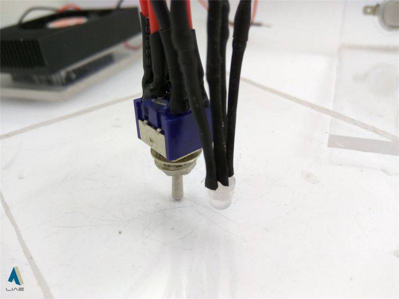
- The toggle switch used to switch between hot and cold gears needs to be fastened with the supplied nut, and must be tightened. Otherwise, the slippery metal can be loosened at the back. After fixing, the six wires are led by the silicone wire. All the feet are drawn


- Then connect the negative pole of the LED to the negative pole of the power supply. The positive pole of the green pin is connected to the positive pole of the power supply. You can see that the LED has been illuminated normally.


- Connect the positive poles at both ends of the toggle switch to the relay output terminal. The negative poles at both ends are connected to the negative pole of the DC step-down module, and the heat-shrinkable tube is used to prevent short circuit.

- Connect the red and blue positive pins of the LED to the pins of the positive and negative poles in the middle of the toggle switch, so that the toggle switch can control the color of the LED, and the adjustment knob can control the middle of the road. Positive and negative poles to control the state of the refrigerant

- Then use 704 silicone rubber to glue the DC step-down module to the base of the acrylic case, the heat sink is facing the cooling fan


- Connect the wires of the cooling fins to the middle two pins of the toggle switch. Also use heat shrink tubing to prevent short circuits


- On the previous basis, connect the modified 7805 buck module to the power supply terminal of the temperature control module.

Then we can start testing its working state and output voltage.

- Connect the cooling fan, cut the yellow speed measuring wire of the fan, and connect it to the power supply side together with the cooling fins


- Use the 705 silicone rubber adhesive sheet to hold the acrylic sheet

- After waiting for it to cure, connect the temperature protection switch and the fan above the cooling plate, and finally use a plastic cable tie to fix a part of the scattered wires.


- After the scattered wires are bundled and finished, the intermediate isolation sink and the control part are glued to a piece of acrylic sheet with 705 silicone rubber.

- Use a firmer hot melt adhesive in the control section to attach a small acrylic plate as a base


- Paste our temperature control board with hot melt adhesive

- Four small foot pads made of hot melt adhesive around the control area

- then make a movable cover to cover the control part


- the overall appearance at this time

- Then take out a roll of aluminum foil and stick it on the 3M tape that looks a bit ugly.


- Stick it outside the incubator

- Then use AB glue to stick a layer of insulation foam, and our work is finished.


Conclusion analysis

- Pour a cup of hot tea to enjoy the afternoon leisure time


- Modulate the voltage of the DC step-down module to 12V

-Inject 1L of cold water at a temperature of about 10 °C with room temperature.

-[size=18.6667px] adjust the temperature control module to the heating position, constant temperature 38 °C,

[size=18.6667px]-An external thermometer is used to measure the depth of the water. It can be seen that after 40 minutes, the temperature will stop at about 40 °C, and the temperature will be slower due to the larger volume of water. You can enjoy a day of hot tea after you come up.

- In terms of refrigeration, due to insufficient heat dissipation at the hot end of the refrigerating sheet, the cold end is only about 4 °C, and the heat dissipation is required. The effect of the small temperature difference in winter is not obvious. The cold-through test is used, and the cooling end can be stabilized at 4. Around °C


- In fact, there are still many applications for this water tank. As for how to use it, you have to use it.

没有评论:
发表评论